atnixon

Experienced Reefer
Rating - 0%
0   0   0
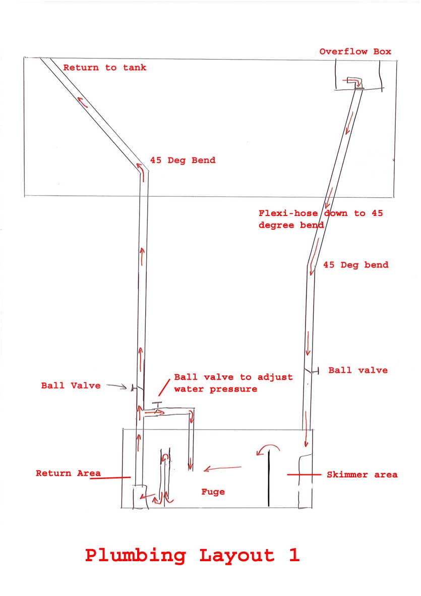
Plans for my home made stand are all but confirmed now..that is near enough job done..Next plans are for the plumbing and sump connection..Can you experienced people have a look over my basic drawing of how i think it should work and please give me some feedback..I do accept constructive criticism very good you know..

Remember, its only a basic drawing so far, just want to make sure that i have the principles right before going on to what pump i need etc etc..

Thanks in advance

Niko
 

Attachments

  • My_sump_and_plumbing_idea___Will_it_Work_.jpg
    My_sump_and_plumbing_idea___Will_it_Work_.jpg
    46.2 KB · Views: 2,735
A

Anonymous

Guest
Rating - 0%
0   0   0
Looks good. Just make sure you have some feature in there for prevent flooding when pump lost power.
 

atnixon

Experienced Reefer
Rating - 0%
0   0   0
Hiya Mate, Cheers for the input...

Well, on the inlet i am going to be using an overflow, so, that should restrict the water from that side, on the return i am going to be using the syphon break method with drilled air holes about an inch below the water level...Hopefully, with them two in place, that i think will combat any flooding should the power or pump fail on me..Would you agree with that?

Niko
 
A

Anonymous

Guest
Rating - 0%
0   0   0
I think you're on the right track.

FWIW here is a link to a DIY pvc overflow I built

http://www.members.aol.com/beaslbob/tan ... erflow.jpg

I suggest you set up a test fixture like this one to test everything out. much better for flood you garage then the living room.

http://www.members.aol.com/beaslbob/tan ... uprevc.jpg

To prevent flooding test for power out operation. and also insure normal operation returns. You will probably find you have to have some anti siphon holes on the pumped return line. but maybe not.

Also simulate an overflow failure. break siphon or plug the overflow. then insure the sump pump starts sucking air before the upper tank floods. Then resume normal operation. And mark the water level on the sump and insure top off does not exceed that level.

But all in all looks like you are on the right track.

my .02
 

PJsea

Reefer
Rating - 0%
0   0   0
You may want to consider putting your refugium on the end with a branch line off your overflow. You can limit the flow to the refugium this way. Otherwise it has full flow from your tank going thru it.
IMO the ball valve on a recirculation line off the return back to the refugium, "to control pressure", is not needed. The valve on the return line can control return flow. The return pumps have very little pressure so you don't need to control it.
I designed my sump with refugium on one end, overflow and skimmer on the other end with the return in the middle. The return plumbing included a branch line to/from a chiller. I don't even have a valve on the main drain line into the sump. I branch off my drain line with 3/4' fitting and valve to control flow to the refugium.

Most people will advise you to get larger piping/fittings to reduce losses. But, there is a big difference in how much space is taken up just between a 1" and 1 1/2" system.
I bought my fittings from HD and was able to lay out my basic setup. I decided to go with the smaller piping/fittings when I saw how much bigger it was with 1 1/2". Ended up exchanging everything.
 

atnixon

Experienced Reefer
Rating - 0%
0   0   0
Thanks PJ for your input..I shall have a look at the changes you suggested on my drawing.. The main reason i put a ball valve on the pipe going back to fuge from the return is because i thought that if there is too much flow going from the return pump, the ball valve which is actually on the return line can limit the flow yes, but would that not create more pressured flow on the fuge return? that is how i understand it...same pressure, going through a smaller hole genertates more back pressure which would cause a high flow going back to fuge??

Please help if i have got this concept wrong please mate..

Your input is vey much appreciated

Niko
 
A

Anonymous

Guest
Rating - 0%
0   0   0
atnixon":2z1g14xw said:
Thanks PJ for your input..I shall have a look at the changes you suggested on my drawing.. The main reason i put a ball valve on the pipe going back to fuge from the return is because i thought that if there is too much flow going from the return pump, the ball valve which is actually on the return line can limit the flow yes, but would that not create more pressured flow on the fuge return? that is how i understand it...same pressure, going through a smaller hole genertates more back pressure which would cause a high flow going back to fuge??

Please help if i have got this concept wrong please mate..

Your input is vey much appreciated

Niko

Given a certain size pump you actually want less pressure in the pipe for more flow (gallons per hour) through the pipe. At a lesser velocity (feet/second). IE a larger diameter pipe. That results in less resistance for the pump to overcome. Longer pump life and cooler operation.

I always thought the "loop" back to the pump intake was a good idea when the pump was too big for the return. Creating more pressure for the pump to over come. So you route some of the output back to the intake so the pump feels less pressure and can operate more efficiently and last longer.

my .02
 

atnixon

Experienced Reefer
Rating - 0%
0   0   0
Hiya Beasl..

that makes sense to me...The pump i am looking at pumps 1700 litres an hour with max height at 2.5 metres...Its a New-Jet1700..

I am thinking of going for about 1" internal diameter pipe work for this..

If i get pjsea's comments right, instead of having the branch off back to the fuge on the return line, i take it he means branching off the intake to the fuge and take that branch into the return area of the sump? ideas on that? or pipe up pjsea to confirm i have got you right...

Am pretty much certain that i am setting the sump/fuge up in the way of the picture, with a slightly smaller inlet area that has the hang on skimmer..2 baffles ( 1st low, 2nd with lower bafle )...fuge in the middle with sand bed, rock and chaeto, then 3 baffles ( 1st low, second with 1 inch gap at the bottom, 3rd low again which is opposite to the picture )...then my return side with a submerged pump..

Any feedback on this so far?

Niko
 
A

Anonymous

Guest
Rating - 0%
0   0   0
My 55g has a mag 5 pumping 4' or so

The when I increased by return lines from 1/2" to 1" I got much increased water flow. So much so that I had to modify my wet/dry to handle the increased flow.

I used the 1/2" originally because that was the output and intake on the pump. So for max flow you need the max diameter possible.

I think splitting the skimmer and refug returns was because refuges do better with lower flow then filter areas. So you split then so less flow goes to the refug.

Some even have the filter on one side, refug on the other with the pump in the center. That way you can set the refug and filter area at different water heights with the baffles. And vary the water flow through both.

But as long as you are not tearing apart your macros and the water is being filtered it should be fine. At anywhere normal flow rates you should be fine either way.

My gut feel is that the return on the return line would not be necessary. But then if you do that all you would have to do is close the valve back to the pump intake. So it wouldn't hurt anything.


I don't know if you have already bought a hob siphon but if not here is a design I came up with using pvc. Worked fine.

20060522overflow.jpg


just my .02
 

atnixon

Experienced Reefer
Rating - 0%
0   0   0
thanks for that explanation beasl..

Can you provide me with more info on that design..I.E..any more pictures, anything you documented when creating it..Pipe diameter etc etc..

Thanks alot mate

Niko
 
A

Anonymous

Guest
Rating - 0%
0   0   0
I used 1 1/4" pipe

1 and 2 are full of water.

What happens is the water overflows at 3 to drain down 4 to the sump.

During power outages the tank drains to just below 3 and the water in 1 and 2 stops flowing. When when power returns, the tank level rises until it overflows at 3 again.

6 primes 2 with water. 5 goes to the pump intake to suck the air out of 1.

here is rev b which has 2 overflows for reduncy and easier mounting:

beaslbobtrapisoview.jpg


And a revision c which has a common water trap between siphons. the center pipe are 2"

20060802isoviewrevc.jpg


But that requires more space behind the tank:

20060802sideviewrevc.jpg


These all operate basically as a skimmer box/hob overflow only without the skimmer box. To operate as a skimmer box you could just run the in tank pvc back up to the surface. That way during power out only the water in the pipe drains to the sump not the entire top of the water in the tank.

Nothing says any of these are the best. So just use these as a starting point. You could undoubtly do better. :D

my .02
 

Christeon

Experienced Reefer
Rating - 0%
0   0   0
It looks to me like your Bubble trap baffles are backwards to me, the center baffle should have the water going under it. As it is drawn you will be sucking the sand out of your refuge area as the water flows under it. You would also lose the surface skimming of the refuge area by having the water leave the through the bottom.
 

trido

Advanced Reefer
Rating - 0%
0   0   0
Christeon":1nxjyc60 said:
It looks to me like your Bubble trap baffles are backwards to me, the center baffle should have the water going under it. As it is drawn you will be sucking the sand out of your refuge area as the water flows under it. You would also lose the surface skimming of the refuge area by having the water leave the through the bottom.

Good catch. I looked at that drawing a couple times and didnt notice the baffles. You are correct. They should be opposite as drawn.

Beaslbob. That looks like a real nice DIY overflow system. Almost flood proof. Not that I can see problems in the design, but you know how things just happen. :wink:
 

atnixon

Experienced Reefer
Rating - 0%
0   0   0
ha ha ha...yes, i know, it has been changed on my drawings...a little bit thick of me to put them that way because of sand creeping up the baffles...

Another thing that has changed is that i was going to using a 30" long tank for the sump, but i have now picked up a 36" long..a little extra water area..Of the 36", can anybody give me an idea of the lengths that each section should be..This is seems to one thing that i cant find any info on..The section with the skimmer does not really need to be that big as its a hang on the back skimmer...

Thanks for the input people..

Niko
 

Christeon

Experienced Reefer
Rating - 0%
0   0   0
I'm making my fuge area the largest of all, my skimmer area is just big enough to fit the skimmer in and runs at a lower water level than the fuge. The return area is your evaporation buffer, if you make it tiny you run the risk of your return pump running dry and having to add water constantly. A top off system would of course solve that issue and it wcould be small. I'm still waiting for all my bits or i'd post some pics.
 

atnixon

Experienced Reefer
Rating - 0%
0   0   0
Well, as its now a 36 long..I am gonna divide it up by inlet section 8"....fuge 14" and return 14"....or maybe fuge 16" and return 14"..

Pipe work is going to be 1" internal diameter..

Just need to figure out how high to do the baffles now..Dont really understand that bit yet..

Niko
 

Christeon

Experienced Reefer
Rating - 0%
0   0   0
This is how i look at the baffles thinking of the wateras it travels through them.

1st wall encloses part of your sump and water flows over it, this wall sets the height in that section. ie if you wanted your fuge at 10" it should be 10" tall


2nd (middle wall in 3 wall baffle) is usually spaced at least 1" away from the first and at least 1" higher, most i've seen have same size piece of glass or Acrylic for all three pieces. This is the wall that actually traps most of the bubbles because the water has to flow underneath it. This wall has no effect on water levels.

3rd wall sets the height of the water in the bubble trap area. You can use it to step the water drop between the 2 sections it seperates. ie. in your drawing if the water level dropped from 10" in the fuge area to 6" in the return area you could make the 3rd wall 8" tall, in effect stepping the water drop down two inches from the fuge to the bubble trap area then another 2" drop to the return area.
 

Sponsor Reefs

We're a FREE website, and we exist because of hobbyists like YOU who help us run this community.

Click here to sponsor $10:


Top